Notes:
- This guidance forms the basis for subsequent installation of a remote control system.
- With this project (as with the loudspeaker installation) it was important to me not to damage any part of the Cappo and for all modifications to be invisible.
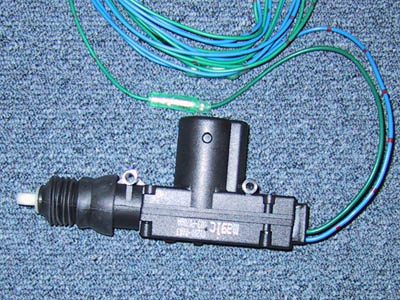
- I tested all electrical connections (Central Locking and remote control) before installation into the car (see picture below). However, in general it's hard to to do anything wrong.
Material:
For the Cappo, I used Waeco's standard Central Locking system, the Magic LOCK ML-44. Waeco is a so-called Original Equipment Manufacturer (OEM) and the kit can be bought from Conrad electronics for DM 99. There is also inexpensive version, the ML-22 for DM 79 or thereabouts.
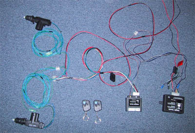
All parts: Central Locking with remote control
Components of the ML-44:
The kit comprises:
2 x Actuators (with sensor = 5 cables) (intended for front doors)
2 x Actuators (without sensor = 2 cables) (intended for rear doors)
1 x Controller
Set of cables and installation hardware
Why ML-44?
As I wanted to use remote control from the outset, I did not need the actuators with sensor.
In the intended installation with the sensor actuators, when the driver's door is opened with the door key, the actuator sends an "open" signal to the other door's actuator via the control unit. However when the remote module is fitted, then both actuators will be simultaneously stimulated, via the control unit, when the remote control is pressed. Actuators with sensors are then not needed, as central locking via key activation is not absolutely necessary.
Advantage: The Cappo is a small car. By using the sensor actuators one would have 5 cables entering the door, plus 2 for the window motors; I do not believe that is not physically viable
Thought: It is possible that the actuators with sensor will work exactly the same as the actuators without sensor, if the additional sensor lines are not used. If so, then the ML-22 kit would do the job. (Though for an extra DM 20, I have two spare actuators in case of failures)
Basics:
Central Locking operates quite simply. First one uses so-called ACTUATORS. These are built into the door. They consist of a housing and a moving plunger (with a throw of about 2cm). This plunger is forced out by supplying +12 Volts and pulled back in with -12 Volts.
Through the use of mechanical linkages, this device provides sufficient force to operate the door lock mechanism.
The controller is fitted in the car interior (on driver's side, there's plenty of room low on the right) and is connected to the actuators via cables. The controller must be permanently powered with 12 V, e.g. from the radio. This device gives both doors a common open/close signal.
Installation of the actuator into the door:
First the door trim must be removed, having already removed the door handle and internal opening lever. The trim itself is held with pushbuttons, which one can be carefully prized up. Unlike many other vehicles, is very easy to remove a Cappo's door trim.
Thus: Remove the door trim and store safely.
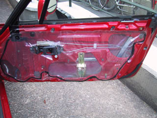
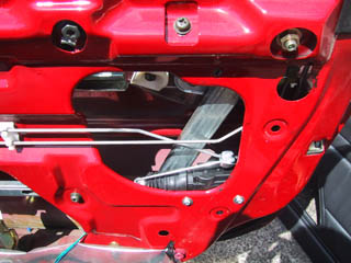
Right door without lining
The inside of the door is covered with a plastic film, fastened with a sticky mastic. The film is best removed at the top and allowed to hang down, thus making it much easier to reposition when finished. If possible do not touch the mastic, which is extremely sticky.
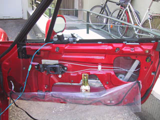
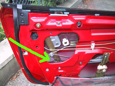
The first question, which I posed myself was: "How do I position an actuator without interfering with the window lift mechanism?" After approximately 1 hour of fiddling I found a suitable position. (see picture)
The actuator's mounting lugs were slightly too wide so I shortened them by about 2 mm each (using a saw). Only then would the unit fit the desired location.
Caution before installation: The window must open and close without interference (test test test).
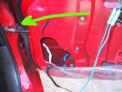
Unfortunately holes in the door must now be drilled. But only small ones.
Then, the actuator is screwed firmly to the door.